Difference between revisions of "Flip Flops"
(→D and T type flippys) |
|||
| Line 16: | Line 16: | ||
==D and T type flippys== | ==D and T type flippys== | ||
| − | + | A flip flop has two inputs. One input is a control input. For a D flip flop, the control input is labelled D. For a T flip flop, the control input is labelled T. The other input is a clock input, labelled either with a triangle or CK. | |
[[File:D-FlipFlop.png|200px]] [[File:D-FlipFlopLogic.png|200px|Logic circuit for a D-Flip Flop]] | [[File:D-FlipFlop.png|200px]] [[File:D-FlipFlopLogic.png|200px|Logic circuit for a D-Flip Flop]] | ||
[[File:T-FlipFlop.png|200px]] [[File:T-FlipFlopLogic.png|200px|Logic circuit for a T-Flip Flop]] | [[File:T-FlipFlop.png|200px]] [[File:T-FlipFlopLogic.png|200px|Logic circuit for a T-Flip Flop]] | ||
Revision as of 11:06, 16 March 2017
Contents
[hide]What is a flip flop
A flip-flop is used to store binary data, and is a simple latching circuit.
Basic (SR) Flip Flops
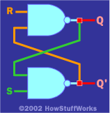
Basic flip flops are created using two NAND gates cross couples as seen in the image.
Problems with basic (SR) flip flops
Edge triggered D Type Flip Flop
D and T type flippys
A flip flop has two inputs. One input is a control input. For a D flip flop, the control input is labelled D. For a T flip flop, the control input is labelled T. The other input is a clock input, labelled either with a triangle or CK.

 200px Logic circuit for a T-Flip Flop

