Difference between revisions of "Half Adder / Full Adder"
(→Full Adder) |
|||
| Line 16: | Line 16: | ||
[[File:Full Adder Blocks.png]] | [[File:Full Adder Blocks.png]] | ||
| + | |||
| + | ==4 Bit Adder== | ||
| + | The 4 bit adder is 4 full adders connected together to allow you to add 2 4 bit binary numbers together. A1, A2, A3, A4 represent 1 binary number, and B1, B2, B3, B4 represent the other binary number. | ||
| + | |||
| + | [[File:4-bit-adder.jpg]] | ||
Revision as of 09:48, 16 March 2017
Half Adder
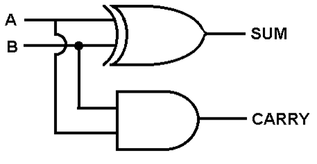
The half adder circuit will do half of a binary addition of 2 1 bit binary numbers. A & B are the 2 1 bit binary values, remember the rules of binary addition:
- 0 1's sum is 0
- 1 1's sum is 1
- 2 1's sum is 0 carry is 1
- 3 1's sum is 1 carry is 1
The most common half adder is made up of two logic gates, an AND gate and a XOR gate. It has two inputs and two outputs. The two inputs are the two bits you are adding together and the two outputs are the result and a carry-on for when the output value is not large enough to display the answer.
Full Adder
The full adder is 2 half adders connected together, this will allow you to add 2 1 bit binary numbers together.
4 Bit Adder
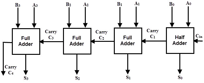
The 4 bit adder is 4 full adders connected together to allow you to add 2 4 bit binary numbers together. A1, A2, A3, A4 represent 1 binary number, and B1, B2, B3, B4 represent the other binary number.


