Difference between revisions of "Flip Flops"
(→D and T type Flip Flops) |
(→D and T type Flip Flops) |
||
| Line 17: | Line 17: | ||
[[File:D-FlipFlop.png|200px]] [[File:D-FlipFlopLogic.png|200px|Logic circuit for a D-Flip Flop]] | [[File:D-FlipFlop.png|200px]] [[File:D-FlipFlopLogic.png|200px|Logic circuit for a D-Flip Flop]] | ||
[[File:D-Type-ff.gif|200px|D type - Flip Flop]] | [[File:D-Type-ff.gif|200px|D type - Flip Flop]] | ||
| + | |||
| + | This works however if the clock remains set, changes in Data will change the output Q. | ||
==Edge triggered D Type Flip Flop== | ==Edge triggered D Type Flip Flop== | ||
Revision as of 18:26, 22 May 2017
Contents
What is a flip flop
A flip-flop is used to store binary data, and is a simple latching circuit. When a value is set on the flip flop, the value is retained even when the input is switched off. This is how you can store a single bit of data in a computers memory.
Basic (SR) Flip Flops
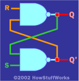
Basic flip flops are created using two NAND gates cross couples as seen in the image.
Problems with basic (SR) flip flops
The downside of the SR Flip Flop is that if both Reset & Set are switched both Q and Not Q are on, which is not allowed. Also if both Reset & Set are changed at the same time from on to off (ie both on to both off) we cannot guarantee the output produced for Q.
D and T type Flip Flops
The issues of the SR flip flop are fixed with the so called Data flip-flop, this is able to ‘latch’ and remember data. It prevents both the indeterminate and non-allowed states of the SR flip-flop. The S and R inputs are now replaced by a single D input, and all D type flip-flops have a clock input.
This works however if the clock remains set, changes in Data will change the output Q.


