Difference between revisions of "Logic Gates"
(→Boolean Logic) |
|||
| Line 1: | Line 1: | ||
| − | |||
| − | |||
| − | |||
| − | |||
| − | |||
| − | |||
| − | |||
| − | |||
| − | |||
| − | |||
=And Gates= | =And Gates= | ||
| Line 27: | Line 17: | ||
| − | + | =NAND Gate= | |
A NAND gate is an inverted AND gate meaning the inputs will cause an inverted outcome, so having no input will cause an output of 1, which is the opposite of an AND gate, which would be 0. | A NAND gate is an inverted AND gate meaning the inputs will cause an inverted outcome, so having no input will cause an output of 1, which is the opposite of an AND gate, which would be 0. | ||
| Line 33: | Line 23: | ||
[[File:Nand Gate.png|200px]] [[File:Nand truth table.png|200px]] | [[File:Nand Gate.png|200px]] [[File:Nand truth table.png|200px]] | ||
| − | + | =NOR Gate= | |
[[File:NOR Gate.png|400px]] | [[File:NOR Gate.png|400px]] | ||
| Line 40: | Line 30: | ||
[[File:Nor gate and truth table.png]] | [[File:Nor gate and truth table.png]] | ||
| − | + | =XOR Gate= | |
An XOR gate is a variation of the OR gate, however, out of its two inputs, it will only give an output of 1 if only one of the inputs is 1, and an output of 0 if both are off or if both are on. | An XOR gate is a variation of the OR gate, however, out of its two inputs, it will only give an output of 1 if only one of the inputs is 1, and an output of 0 if both are off or if both are on. | ||
[[File:XOR Gate.png|300px]] [[File:Truth table xor.png]] | [[File:XOR Gate.png|300px]] [[File:Truth table xor.png]] | ||
| + | |||
| + | |||
| + | =Boolean Logic= | ||
| + | <youtube>https://www.youtube.com/watch?v=1tEkjOcCAMU&index=1&list=PLCiOXwirraUA9HyHoqOaGBU_k6nBRCb22</youtube> | ||
| + | |||
| + | https://www.youtube.com/watch?v=1tEkjOcCAMU&index=1&list=PLCiOXwirraUA9HyHoqOaGBU_k6nBRCb22 | ||
| + | |||
| + | =Boolean & Circuits= | ||
| + | <youtube>https://www.youtube.com/watch?v=41Xa1hDl5K0&index=2&list=PLCiOXwirraUA9HyHoqOaGBU_k6nBRCb22</youtube> | ||
| + | |||
| + | https://www.youtube.com/watch?v=41Xa1hDl5K0&index=2&list=PLCiOXwirraUA9HyHoqOaGBU_k6nBRCb22 | ||
=Drawing Circuits from Equations= | =Drawing Circuits from Equations= | ||
Revision as of 09:43, 11 June 2018
Contents
[hide]And Gates
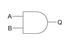
The output of an AND gate is true only when all of the inputs are true. If one or more of an AND gate's inputs are false, then the output of the AND gate is false.
Or Gates
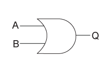
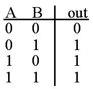
An OR gate is when either of the values can be true, and the output shall always be true in that instance. The images below shows what the OR gate looks like, and the table shows all possible outcomes.
Not Gates
A NOT gate outputs the opposite of what is inputted. The image below shows a NOT gate, as well as all possible outcomes.
NAND Gate
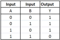
A NAND gate is an inverted AND gate meaning the inputs will cause an inverted outcome, so having no input will cause an output of 1, which is the opposite of an AND gate, which would be 0.
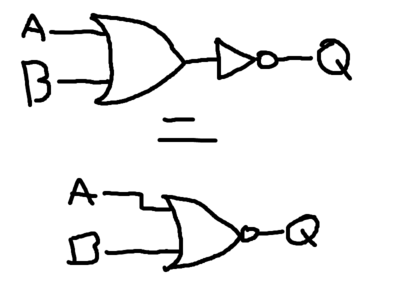
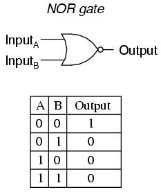
NOR Gate
A NOR gate is an inverted OR gate, so any input will cause an output of 0 and this is the opposite of a regular OR gate, which would give an output of 1.
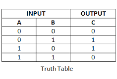
XOR Gate
An XOR gate is a variation of the OR gate, however, out of its two inputs, it will only give an output of 1 if only one of the inputs is 1, and an output of 0 if both are off or if both are on.
Boolean Logic
https://www.youtube.com/watch?v=1tEkjOcCAMU&index=1&list=PLCiOXwirraUA9HyHoqOaGBU_k6nBRCb22
Boolean & Circuits
https://www.youtube.com/watch?v=41Xa1hDl5K0&index=2&list=PLCiOXwirraUA9HyHoqOaGBU_k6nBRCb22
Drawing Circuits from Equations
https://www.youtube.com/watch?v=YhZJKquQbS4&list=PLCiOXwirraUA9HyHoqOaGBU_k6nBRCb22&index=3
